NHD-C0220BiZ-FSW-FBW-3V3M issues with TI MSP432P401R launchpad

Hi,
First time using i2C. As per page 4 of the Data sheet,
I have C = 1uF, 16V.
R (The pullups) on SDA and SCL are 10kohms each.
I have a 1kohm pullup on RST and a 1kohm resistor from the Anode of the backlight to the 3.19V power supply.
I have a 0.1uF bypass capacitor across Vdd and Vss.
I am single stepping through my code and have a breakpoint set at 'line 1)' below
#define SLAVE_ADDRESS 0x78
....................................
1) MAP_I2C_masterSendSingleByte(EUSCI_B1_BASE, SLAVE_ADDRESS);
2) MAP_I2C_masterSendSingleByte(EUSCI_B1_BASE, 0x00);
When i step through at line 1, program does not exit to line 2
On halting, the code is hung up at last line in the module segment shown below.
void I2C_masterSendSingleByte(uint32_t moduleInstance, uint8_t txData)
{
    //Store current TXIE status
    uint16_t txieStatus = EUSCI_B_CMSIS(moduleInstance)->rIE.r & UCTXIE;

    //Disable transmit interrupt enable
    BITBAND_PERI(EUSCI_B_CMSIS(moduleInstance)->rIE.r,UCTXIE_OFS) = 0;

    //Send start condition.
    EUSCI_B_CMSIS(moduleInstance)->rCTLW0.r |= UCTR + UCTXSTT;

    //Poll for transmit interrupt flag.
    while (!(EUSCI_B_CMSIS(moduleInstance)->rIFG.r & UCTXIFG))
        ;

    //Send single byte data.
    EUSCI_B_CMSIS(moduleInstance)->rTXBUF.r = txData;

    //Poll for transmit interrupt flag.
    while (!(EUSCI_B_CMSIS(moduleInstance)->rIFG.r & UCTXIFG))
        ;
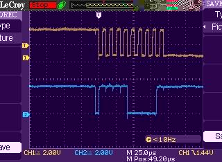
Attached is a screenshot when i execute line 1 (MAP_I2C_masterSendSingleByte(EUSCI_B1_BASE, SLAVE_ADDRESS)
Top plot is SCL
Bottom plot is SDA
These are voltage measurements
RST (Pin1) 3.187 V
VDD (Pin5) 3.188 V
VOUT (Pin6) 2.82 V
C1+ (Pin7) 3.17 V
C1- (Pin8) 0.015 V
A - 2.5 V
K - 0 V
-

Hello,
Looking at your trace, it looks like you're clocking in the SDA on the falling edge.
When you are sending the Address, it looks like you are sending a 0xF0 instead of the 78. Would you be able to try 0x3C for your address?0 -
Thanks,
I changed to 0x3C and can now perform the LCD initialization. And i have the cursor displayed.
Help needed on how to switch to writing a character. Using the following code did not work.#define SLAVE_ADDRESS 0x3C
1) MAP_I2C_masterSendMultiByteStart(EUSCI_B1_BASE, SLAVE_ADDRESS); // Start Transmission and send address 0x3C
2) MAP_I2C_masterSendMultiByteNext(EUSCI_B1_BASE, 0x40); // data mode
3) MAP_I2C_masterSendMultiByteNext(EUSCI_B1_BASE, 0x46); // Ascii 'D'
4) MAP_I2C_masterSendMultiByteStop(EUSCI_B1_BASE); // End TransmissionWhen i execute line 2, the cursor jumps to the start of the 2nd line.Next when i execute line 3, the cursor moves
to 6 locations to the right.
It looks like I still have 'RS=0'
How can i change to having 'RS=1', so that data sent will go to the RAM and be subsequently displayed.
Below is my LCD initialization code. e.g my48Mdelayms(40) creates a delay of 40ms.my48Mdelayms(40);
MAP_I2C_masterSendMultiByteStart(EUSCI_B1_BASE, SLAVE_ADDRESS); // Send Start followed by Start address
MAP_I2C_masterSendMultiByteNext(EUSCI_B1_BASE, 0x00);
MAP_I2C_masterSendMultiByteNext(EUSCI_B1_BASE, 0x38); //Function set - 8 bit, 2 line display 5x8, inst table 0
my48Mdelayms(10);
MAP_I2C_masterSendMultiByteNext(EUSCI_B1_BASE, 0x39); //Function set - 8 bit, 2 line display 5x8, inst table 1
my48Mdelayms(10);
MAP_I2C_masterSendMultiByteNext(EUSCI_B1_BASE, 0x14); // Set bias - 1/5
MAP_I2C_masterSendMultiByteNext(EUSCI_B1_BASE, 0x78); // Set contrast low
MAP_I2C_masterSendMultiByteNext(EUSCI_B1_BASE, 0x5E); // ICON disp on, Contrast high byte
MAP_I2C_masterSendMultiByteNext(EUSCI_B1_BASE, 0x6D); // Follower circuit (internal), amp ratio (6)
my48Mdelayms(300);
MAP_I2C_masterSendMultiByteNext(EUSCI_B1_BASE, 0x0E); // Display on, cursor on
MAP_I2C_masterSendMultiByteNext(EUSCI_B1_BASE, 0x01); // Clear display
my48Mdelayms(2);
MAP_I2C_masterSendMultiByteNext(EUSCI_B1_BASE, 0x06); // Entry mode set - increment
my48Mdelayms(2);
MAP_I2C_masterSendMultiByteStop(EUSCI_B1_BASE); // End Transmission0 -
Thanks all,
I have fixed the issue. I will post the code in another thread to help others in future.
The main issue had to do with using the API:MAP_I2C_masterSendMultiByteStart(EUSCI_B1_BASE, xx)
This API does the following:
- Sends START
- Sends 7-bit Device address
- Sends byte xx.
To enable command mode, i have to send:
MAP_I2C_masterSendMultiByteStart(EUSCI_B1_BASE, 0x40);
To enable data mode , i have to send:
MAP_I2C_masterSendMultiByteStart(EUSCI_B1_BASE, 0x40);0
Please sign in to leave a comment.
Comments
3 comments