NHD-C0216CiZ-FSW-FBW-3V3 with arduino nano

Dear all,
I have this(NHD-C0216CiZ-FSW-FBW-3V3) display and arduino nano. But after a lot of trials, i could not get it working. Please help.
I have made connections as per the datasheet.
RST: high to 3.3V
VDD to 3.3V
VSS to GND
Vout connected to VDD through a 1uF cap
C- an C+ connected together through a 1uF cap
SCL to D5(Arduino)
SCL to D4(Arduino)
Could not figure out what is wrong. Tried some arduino code from the forum. Bot nothing works.

-

Hello,
It looks like you have the display wired backwards. Pin 1 of the display is on the right side of the display. Please see picture below: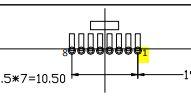
I would also recommend the use of a level shifter (5V to 3V) for the data lines. While you do have the display powered with 3.3V the voltage levels on D4 & D5 will still be ~5V when powered via USB.
This can damage the controller and the display over time, thus reducing the overall lifetime of the display.
I have an example i wrote to work with an arduino Mega here:/*****************************************************/
/*
C0216CiZ.c
This program is free software; you can redistribute it and/or modify
it under the terms of the GNU General Public License as published by
the Free Software Foundation; either version 2 of the License, or
(at your option) any later version.
This program is distributed in the hope that it will be useful,
but WITHOUT ANY WARRANTY; without even the implied warranty of
MERCHANTABILITY or FITNESS FOR A PARTICULAR PURPOSE. See the
GNU General Public License for more details.
*/
/*****************************************************/
/*****************************************************/
unsigned char text1[]={"NEWHAVEN Display"};
unsigned char text2[]={"2x16 LCD Module "};
unsigned char text3[]={0x00,0x01,0x02,0x03,0x04,0x05,0x06,0x07,0x08,0x09,0x0a,0x0b,0x0c,0x0d,0x0e,0x0f};
unsigned char text4[]={0x10,0x11,0x12,0x13,0x14,0x15,0x16,0x17,0x18,0x19,0x1a,0x1b,0x1c,0x1d,0x1e,0x1f};
/*****************************************************/
#define SDO 22 //Serial data
#define SCLK 23 //Serial clock
#define RESET 24 //RESETET
/*****************************************************/
const char Slave = 0x7C;
const char Comsend = 0x00;
const char Datasend = 0x40;
const char Line2 = 0xC0;
/*****************************************************/
/*****************************************************/
void I2C_out(unsigned char j) //I2C Output
{
int n;
unsigned char d;
d=j;
for(n=0;n<8;n++){
if((d&0x80)==0x80)
digitalWrite(SDO, HIGH);
else
digitalWrite(SDO, LOW);
d=(d<<1);
digitalWrite(SCLK, LOW);
digitalWrite(SCLK, HIGH);
digitalWrite(SCLK, LOW);
}
digitalWrite(SCLK, HIGH);
while(SDO==HIGH){
digitalWrite(SCLK, LOW);
digitalWrite(SCLK, HIGH);
}
digitalWrite(SCLK, LOW);
}
/*****************************************************/
void I2C_Start()
{
digitalWrite(SCLK, HIGH);
digitalWrite(SDO, HIGH);
digitalWrite(SDO, LOW);
digitalWrite(SCLK, LOW);
}
/*****************************************************/
void I2C_Stop()
{
digitalWrite(SDO, LOW);
digitalWrite(SCLK, LOW);
digitalWrite(SCLK, HIGH);
digitalWrite(SCLK, HIGH);
}
/*****************************************************/
void Show(unsigned char *text) // Display text
{
int n, d;
d=0x00;
I2C_Start();
I2C_out(Slave);
I2C_out(Datasend);
for(n=0;n<16;n++){
I2C_out(*text);
++text;
}
I2C_Stop();
}
/*****************************************************/
void nextline(void) // Move to Line 2
{
I2C_Start();
I2C_out(Slave);
I2C_out(Comsend);
I2C_out(Line2);
I2C_Stop();
}
void CGRAM (void)
{
I2C_Start();
I2C_out(Slave);
I2C_out(Comsend);
I2C_out(0x38); //go to instructino table 0
I2C_out(0x40); //Set CGRAM addRESETs to 0x00
I2C_Stop();
delay(10);
I2C_Start();
I2C_out(Slave);
I2C_out(Datasend);
I2C_out(0x00); //write to first CGRAM addRESETs
I2C_out(0x1E);
I2C_out(0x18);
I2C_out(0x14);
I2C_out(0x12);
I2C_out(0x01);
I2C_out(0x00);
I2C_out(0x00); //8 bytes per character
I2C_out(0x00);
//continue writing to remaining CGRAM if desired
I2C_Stop();
}
/****************************************************
* Initialization For ST7032i *
*****************************************************/
void init_LCD()
{
I2C_Start();
I2C_out(Slave);
I2C_out(Comsend);
I2C_out(0x38);
delay(10);
I2C_out(0x39);
delay(10);
I2C_out(0x14);
I2C_out(0x78);
I2C_out(0x5D);
I2C_out(0x6D);
I2C_out(0x0C);
I2C_out(0x01);
I2C_out(0x06);
delay(10);
I2C_Stop();
//CGRAM(); //define CGRAM
I2C_Start();
I2C_out(Slave);
I2C_out(Comsend);
I2C_out(0x39);
I2C_out(0x01); //go back Home
I2C_Stop();
delay(10);
}
/*****************************************************/
/*****************************************************/
void setup() {
pinMode(RESET, OUTPUT);
pinMode(SDO, OUTPUT);
pinMode(SCLK, OUTPUT);
digitalWrite(RESET, LOW);
delay(10);
digitalWrite(RESET, HIGH);
delay(100);
}
void loop() {
init_LCD();
delay(2);
Show(text1);
nextline();
Show(text2);
delay(2500);
while(1){
digitalWrite(SDO, HIGH);
delay(1000);
}
}0 -
Thank you very much...I changed the connection from right to left.
Pin 4- SDA
Pin 5- SCLK
Pin 3- ResetBut I don't see any response.....

please suggest....!0 -
Can you tell me if what the voltage on pin 6 (VOUT) is?
If the voltage booster circuit does not activate it could mean that your instructions are not being read by the display. Do you by any chance have a logic analyzer?
This would help you see if the right data is being input into the display.0
Please sign in to leave a comment.
Comments
3 comments