Color Artifacts After Migrating from 480x272 ATXL to ASXP Model
Answered
Hello everyone,
I am in the process of migrating my system from an older Newhaven display to a newer model.
-
Old Display: 480x272 (ATXL series)
-
New Display: 480x272 (ASXP series)
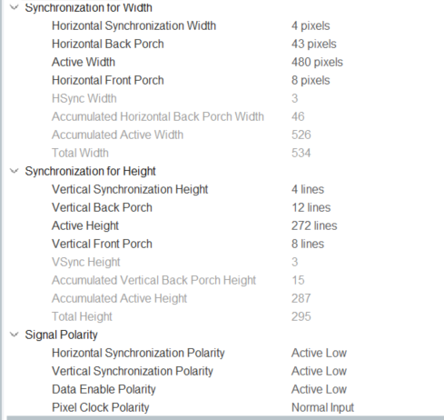
I have carefully updated my display driver configuration to match the new ASXP model's datasheet, including all timings (clock frequency, H/V width, porch settings, etc.). The display initializes and works, but I am facing a problem with color reproduction.
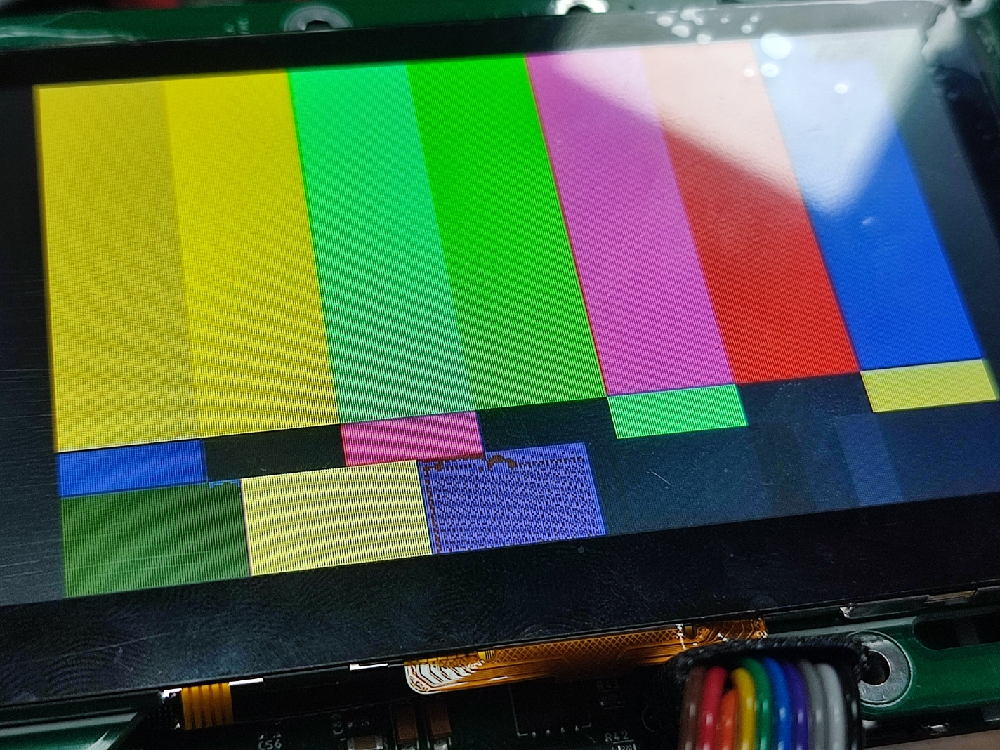
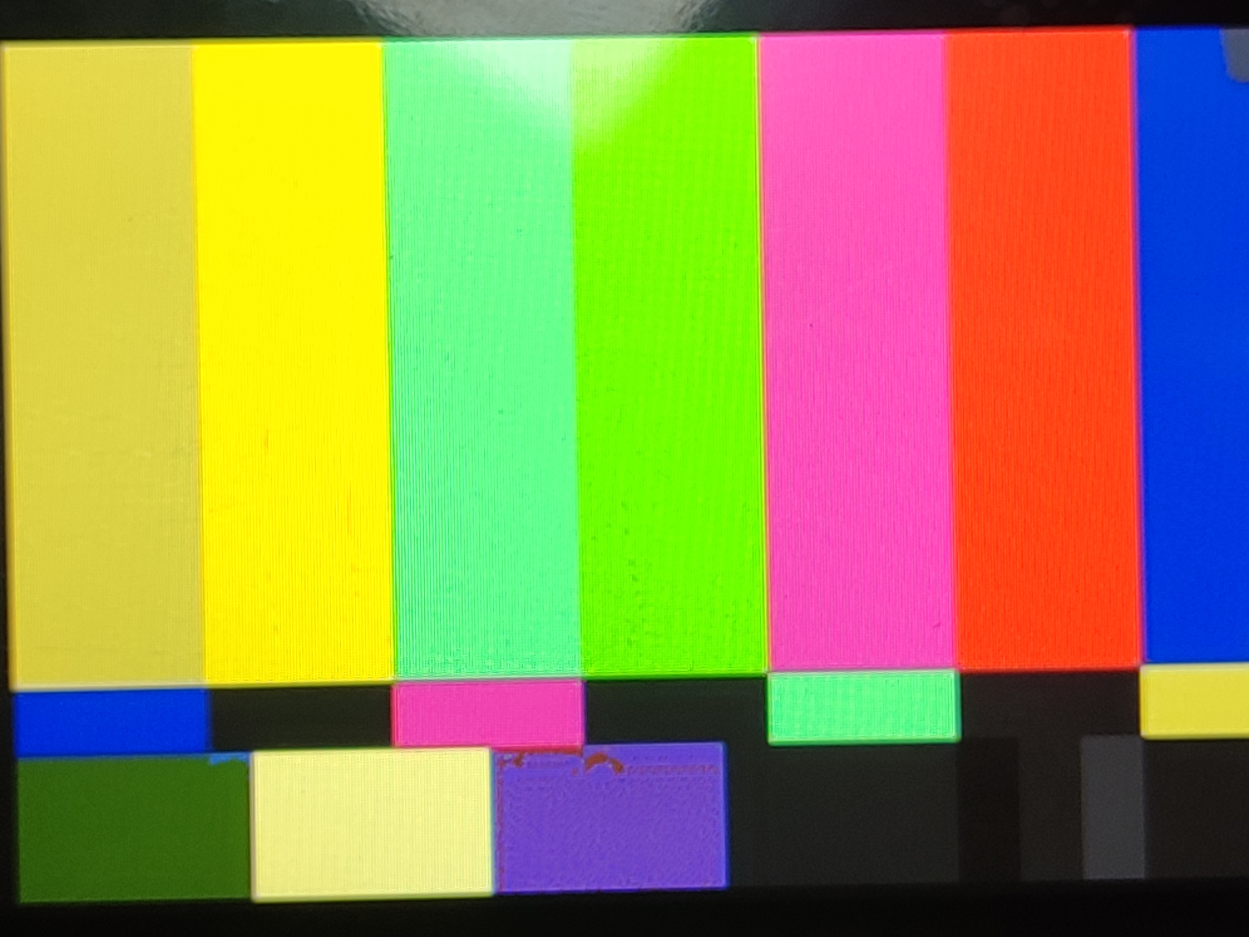
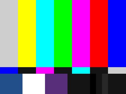
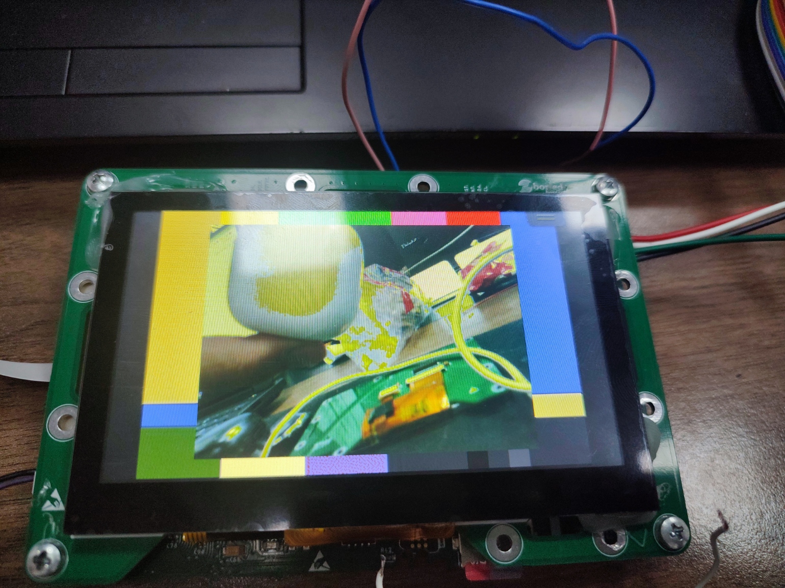
I've noticed that the issue is particularly bad in areas where the blue color is being mixed or blended with other colors (for example, in gradients). When blending from Red to Blue (magenta) or from Blue to Green (cyan), I see hard lines and artifacts instead of a smooth transition.
I am attaching several images to show the problem.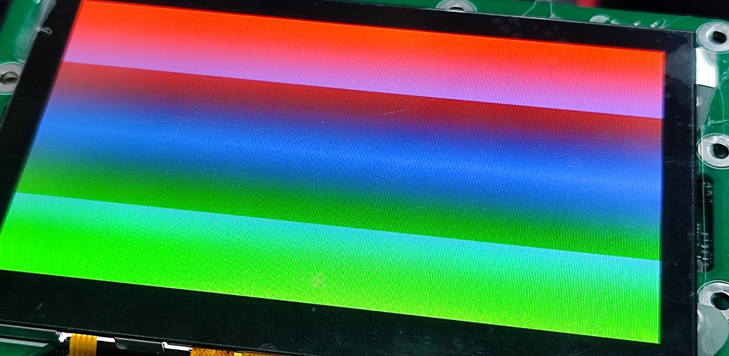
-
Official comment

Hi Furkan,
Is your CLKIN signal using the rising edge? This could be causing the harsh lines for gradients.
-
These are the settings for my STM32F7 project. Honestly, I couldn't completely figure out how to choose these settings from the display's datasheet; there are too many figures. But the previous display worked flawlessly with these settings.
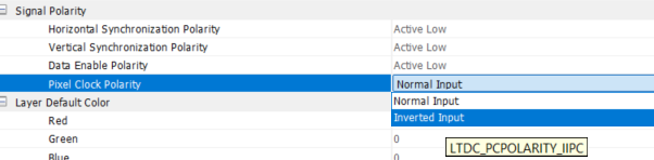
Do I need to change the pixel clock polarity setting? Oddly, after reading your message, I tried both normal and inverted modes, and both gave me the same result. I expected the result to change significantly, as it seemed like one of the most critical settings to me. Is it normal for nothing to change, or did I perhaps fail to upload the code correctly?
 0
0 -
This is a real-time camera feed. All the whitish colors turn distinct yellow. Again, the older screen has no problems with it. Also tried a different screen with the same model.
 0
0 -
Hi Furkan,
Can you try setting the Data Enable Polarity as active high and see if that fixes the issue?

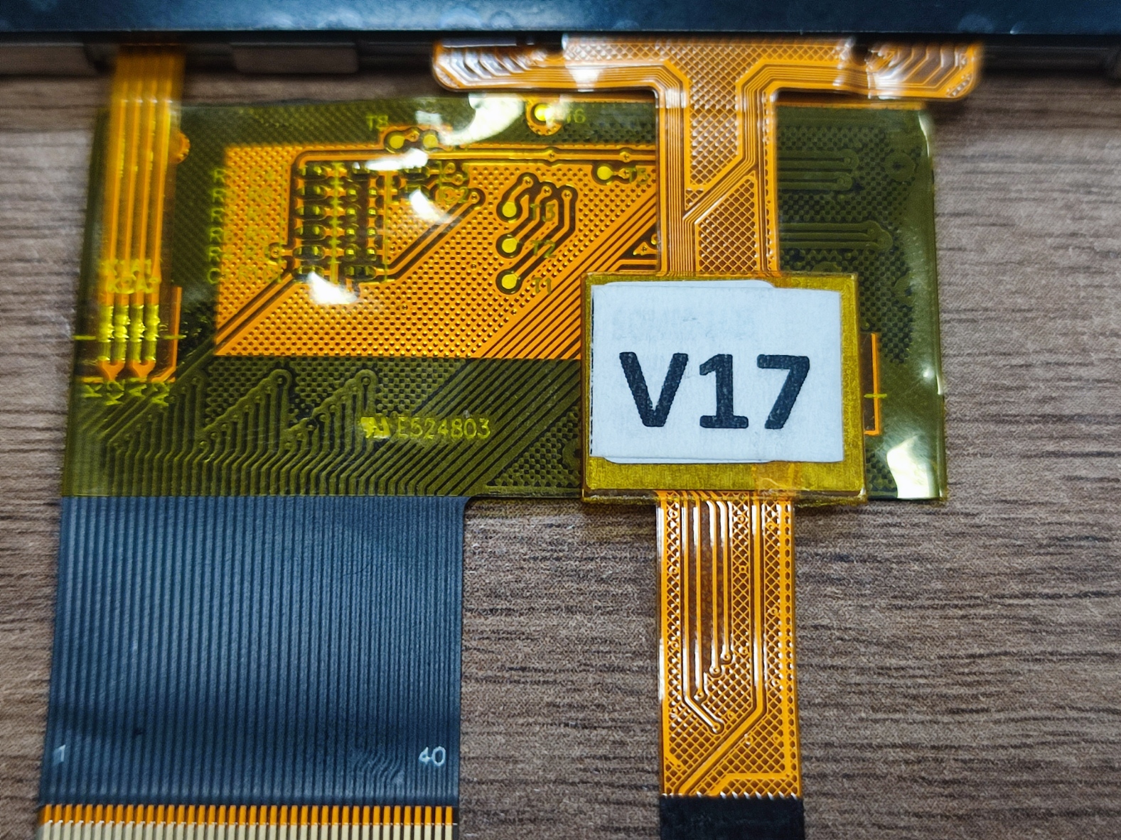
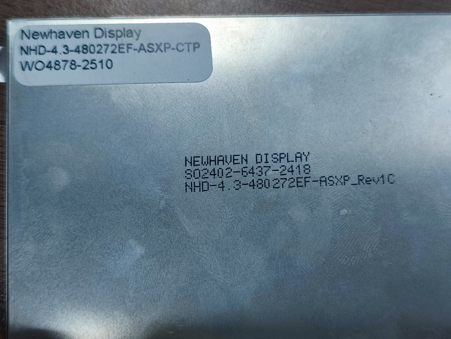
Could I also get a picture of the back of the old screen that worked so I can check the date code?
0 -
Did you mean these settings? I already tried, and nothing changed.
 0
0 -
Could you also try to change the Data Enable Polarity to active high?
0 -
With old screen:
pclk pol is inverted, and DE is active low; the image is rendered with no problem.
pclk pol is normal, and DE is active low; the image is rendered without issues.
pclk pol is inverted, and DE is active high: no image, just some random white vertical lines.
With new ASXP screen:
pclk pol is inverted, and DE is active low: The same problems mentioned above persist, resulting in false colors.
pclk pol is normal, and DE is active high: The same issues mentioned above persist, resulting in false colors.
pclk pol is inverted, and DE is active high: The same issues mentioned above persist, resulting in false colors.
It's like a new screen doesn't bother these settings.0 -
Thank you for testing the different settings. Could I get a picture of the back of the display? This is so I can see the date code.
0 -
 0
0 -
Hi Furkan,
Thank you for the date codes. I wanted to ask what your RGB mode is?
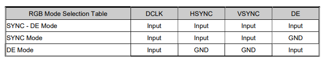
You need to correctly set the RGB interface mode to utilize the relevant pins. Some pins need to be connected to GND depending on the mode selected for the display.
0 -
Hello again.
To be honest, I’m not entirely sure which mode the display is operating in. However, I’m using the LTDC interface of the STM32, and this interface includes the four signals you mentioned above. Logically, the display should be operating in sync-de mode.
0 -
Could you please provide your wiring diagram for the display? I also wanted to ask is your LTDC configuration setup for 24-bit RGB interface?
0 -
My last message is still waiting for approval.
0 -

Hello Furkan, I'm having the same issue with my screen. Were you able to solve the problem?
0 -
Hello everyone,
It turns out the issue was not related to the Display Panel compatibility, LTDC Timings, or the PCB Design. The root cause was a manufacturing defect (Cold Solder Joint) on the Board-to-Board (BTB) connector of the specific PCB unit I was using for testing.
The Troubleshooting Trap (The "Bad Luck" Scenario): We have a batch of 10 identical PCBs assembled by a third-party.
-
By chance, the specific unit I picked from the batch to test the new ASXP screen happened to have a soldering defect on the BTB connector.
-
When the screen showed artifacts, I naturally blamed the new display settings/compatibility, assuming the PCB was fine since it was fresh from production.
-
The old ATXL screens were never mounted on this specific faulty unit, so we had no baseline comparison for this specific board.
The Solution: The breakthrough happened when we decided to try the new ASXP screen on a second PCB unit from the exact same batch. It worked immediately with standard datasheet settings.
Returning to the first "faulty" PCB, we inspected the BTB connector, applied flux, and reflowed the pins. The artifacts disappeared, and the unit is now working perfectly.
Lesson Learned: When testing a new component on a new batch of PCBs, never rely on a single unit. A manufacturing defect on your "test mule" can easily mislead you into debugging software for days. Always cross-check with a second board!
Thanks for the support.
0 -
-
Hi Furkan,
That's great to hear you got the display working properly! Thank you also for the detailed information on how you got the issues with the display resolved.
0
Please sign in to leave a comment.
Comments
16 comments