NHD-1.1-9696G

Hi,
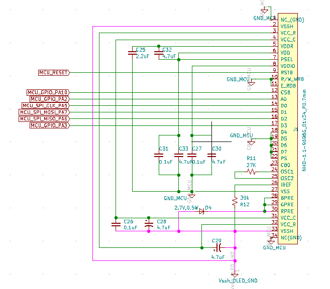
I am currently working on NHD-1.1-9696G for my project, which communicates with a P-NUCLEO-WB55 evaluation board (based on STM32 MCU) over 4-wire SPI protocol. The display circuit is as per the wiring diagram provided in the display datasheet (please refer attachment).
I had initially powered VDD and VDDIO from a separate source but found that the voltage between MCU output pins and display GND was 4.3 V. Now, I am powering VDD, VDDIO at 3.3V and VSS (GND) from the MCU board, which in turn is powered through the debug port (USB) when connected to the PC. The VCCR (12V) and VSSH (GND) is powered by a separate 12V regulator, which can supply at least 200 mA.
Looks like I am able to communicate with the display as the write messages are being executed one after another during the initialization sequence (as viewed on the debugger). However, I am unable to switch on the display even after writing the value 0x01 to the index register 0x02. Also, I am unable to read from the index registers and check their values.
(EDIT: Please check my latest messages below for an update. Now I'm able to write and read to index registers)
Can you please help me with any verification method to test if the display is fine or if its damaged?
regards,
Kishan
-
Hi,
I had not connected SDO pin (D2) as it was mentioned in the SEPS114 datasheet that in the SPI mode, it should not be connected. I took a risk and connected the SDO pin to MCU MISO and I am now able to read the index values as well.
It is confirmed that the values are getting written to the index registers and also being able to read. The initialization sequence is as per the example provided in the NHD-1.1-9696G datasheet (page 13).
However, still not getting the display On. Kindly help.
regards,
Kishan0 -
Below is my initialization sequence. Please let me know if I have to modify.
OLED_RESET_LOW();
OLEDStatus = OLED_RESET;
OLED_Delay(10);
OLED_RESET_HIGH();
OLED_Delay(10);
OLED_Write(OLED_SOFT_RESET, 0x00);
OLED_Write(OLED_STANDBY_ON_OFF, 0x01);
OLED_Delay(1);
OLED_Write(OLED_STANDBY_ON_OFF, 0x01);
OLED_Delay(1);
OLED_Write(OLED_DISP_ON_OFF, 0x00);
OLED_Write(OLED_ANALOG_CONTROL, 0x40);
OLED_Write(OLED_OSC_ADJUST, 0x03);
OLED_Write(OLED_DISPLAY_X1, 0x00);
OLED_Write(OLED_DISPLAY_X2, 0x5F);
OLED_Write(OLED_DISPLAY_Y1, 0x00);
OLED_Write(OLED_DISPLAY_Y2, 0x5F);
OLED_Write(OLED_RGB_IF, 0x00);
OLED_Write(OLED_RGB_POL, 0x00);
OLED_Write(OLED_DISPLAY_MODE_CONTROL, 0x80);
OLED_Write(OLED_CPU_IF, 0x00);
OLED_Write(OLED_ROW_SCAN_DIRECTION, 0x00);
OLED_Write(OLED_ROW_SCAN_MODE, 0x00);
OLED_Write(OLED_COLUMN_CURRENT_R, 0x6E);
OLED_Write(OLED_COLUMN_CURRENT_G, 0x4F);
OLED_Write(OLED_COLUMN_CURRENT_B, 0x77);
OLED_Write(OLED_ROW_OVERLAP, 0x00);
OLED_Write(OLED_DISCHARGE_TIME, 0x01);
OLED_Write(OLED_PEAK_PULSE_DELAY, 0x0);
OLED_Write(OLED_PEAK_PULSE_WIDTH_R, 0x02);
OLED_Write(OLED_PEAK_PULSE_WIDTH_G, 0x02);
OLED_Write(OLED_PEAK_PULSE_WIDTH_B, 0x02);
OLED_Write(OLED_PRECHARGE_CURRENT_R, 0x14);
OLED_Write(OLED_PRECHARGE_CURRENT_G, 0x50);
OLED_Write(OLED_PRECHARGE_CURRENT_B, 0x19);
OLED_Write(OLED_ROW_SCAN_ON_OFF, 0x00);
OLED_Write(OLED_SCAN_OFF_LEVEL, 0x04);
OLEDStatus = OLED_OK;
OLED_ClearScreen(); /* routine to write all bits in DDRAM to 0x0 */
OLED_Write(OLED_DISPLAYSTART_X, 0x00);
OLED_Write(OLED_DISPLAYSTART_Y, 0x00);
OLED_Write(OLED_DISP_ON_OFF, 0x01);
OLED_Delay(100);
OLED_SetDDRAMSize(0x00, 0x5F, 0x00, 0x5F);
OLED_SetDisplaySize(0x00, 0x5F, 0x00, 0x5F);
Is there any troubleshooting that i can do in terms of wiring connection or in the driver to check what's wrong?
regards,
Kishan0 -
Hi,
I am currently working on NHD-1.1-9696G for my project, which communicates with a P-NUCLEO-WB55 evaluation board (based on STM32 MCU) over 4-wire SPI protocol. The display circuit is as per the wiring diagram provided in the display datasheet (please refer attachment).
I had initially powered VDD and VDDIO from a separate source but found that the voltage between MCU output pins and display GND was 4.3 V. Now, I am powering VDD, VDDIO at 3.3V and VSS (GND) from the MCU board, which in turn is powered through the debug port (USB) when connected to the PC. The VCCR (12V) and VSSH (GND) is powered by a separate 12V regulator, which can supply at least 200 mA.
I had not connected SDO pin (D2) as it was mentioned in the SEPS114 datasheet that in the SPI mode, it should not be connected. I took a risk and connected the SDO pin to MCU MISO and I am now able to read the index values as well.
It is confirmed that the values are getting written to the index registers and also being able to read. The initialization sequence is as per the example provided in the NHD-1.1-9696G datasheet (page 13).
Hi,
Please let me know if there's any resolution available for the problem started earlier as I am not able to figure it out by myself and my project is not making any further progress. Do let me know if I need to share any other information.
Kindly help.
Looking forward to hearing from you.
Regards,
Kishan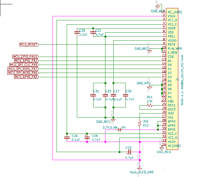 « Last Edit: November 29, 2019, 08:49:49 AM by kishanmbhat »0
 -

Hi Kishan,
Here is some working Arduino example code on our Github site that may help you to test the display.
https://github.com/NewhavenDisplay/NHD-1.1-9696G
Best Regards,0 -
Hi Ted,
Thanks for the example code. Let me test this and revert to you.
regards,
Kishan0
Please sign in to leave a comment.
Comments
5 comments