NHD-2.4-240320CF-CTXI#-F Display Not Responding

I am attempting to interface this display with an Arduino as a practice run before I move further into my design. I found this post earlier
https://support.newhavendisplay.com/hc/en-us/community/posts/11071472754711--Sample-Code-for-NHD-2-4-240320CF-CTXI-with-UNO-or-Metro
which has very helpful code. But when I follow the setup described in the files and upload the sketch to my arduino the display just dims a bit.
When I use the example code provided in the Application Notes section there is no visible change. What reasons might be causing this issue?
-
When I run the attached code on my display module the display turns off then on which is expected as I send the display off command then the display on command during initialization. After that I attempt to change the screen to a solid colour but there is no change in colour. Maybe there is something wrong with my code. Could someone please review it? It is for the Arduino Uno Rev 3.
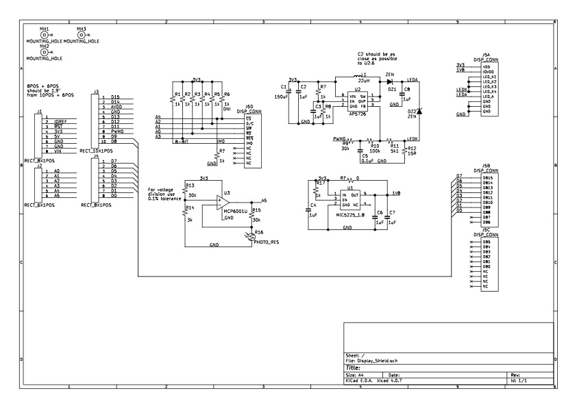
I have also attached a PDF of my schematic in case anyone wants to see if I made a mistake in hardware/*
* HW RESET DEFAULT:
* o 18 bpp
* o Sleep
*
* CONTROL LINES:
* nCS - NA, tied to ground
* nRES - A3
* DC - A2
* nWR - A1
* nRD - A0
*
* DATA LINES:
* D[1:0] - D9:D8
* D[7:2] - D7:D2
*/
int nRS = A3; // Active low reset
int DC = A2; // Data/Command
int nWR = A1; // Active low write
int nRD = A0; // Active low read
// 18bpp or 16bpp
#define MODE_18BPP
#ifdef MODE_18BPP
/* 8080-II 8-bit 18 bpp format
* (0brrrr_rggg_ggbb_bbbx)
* x: LSB of all colours
*/
#define RED (0xF800)
#define GREEN (0x07C0)
#define BLUE (0x003E)
#else
/* 8080-II 8-bit 16 bpp format
* (0brrrr_rggg_gggb_bbbb)
*/
#define RED (0xF800)
#define GREEN (0x07E0)
#define BLUE (0x001F)
#endif
void TFT_SEND_CMD(uint8_t cmd) {
PORTC |= 0x09; // Set nWR and DC pins low
PORTB &= (0x03 & cmd);
PORTD &= (0xFC & cmd);
delayMicroseconds(1);
PORTC |= 0x0B; // Set nWR pins high
delayMicroseconds(1);
PORTC |= 0x0F; // Set DC pin high
}
void TFT_SEND_DATA(uint8_t dat) {
PORTC |= 0x0D; // Set nWR pin low
PORTB &= (0x03 & dat);
PORTD &= (0xFC & dat);
delayMicroseconds(1);
PORTC |= 0x0F; // Set nWR pins high
delayMicroseconds(1);
}
void TFT_INIT(void) {
// Turn display off
TFT_SEND_CMD(0x28);
// Exit sleep mode
TFT_SEND_CMD(0x11);
delay(10);
TFT_SEND_CMD(0x36);
TFT_SEND_CMD(0x36); //MADCTL: memory data access control
TFT_SEND_DATA(0x80); // MY (row address order) = 1 :: MX,MV,ML,RGB = 0
#ifdef MODE_18BPP
TFT_SEND_CMD(0x3A); //COLMOD: Interface Pixel format *** 262K-colors in 18bit/pixel format when using 8-bit interface to allow 3-bytes per pixel
TFT_SEND_DATA(0x66);
#else
TFT_SEND_CMD(0x3A); //COLMOD: Interface Pixel format *** 65K-colors in 16bit/pixel (5-6-5) format when using 16-bit interface to allow 1-byte per pixel
TFT_SEND_DATA(0x55);
#endif
TFT_SEND_CMD(0xB2); //PORCTRK: Porch setting
TFT_SEND_DATA(0x0C);
TFT_SEND_DATA(0x0C);
TFT_SEND_DATA(0x00);
TFT_SEND_DATA(0x33);
TFT_SEND_DATA(0x33);
TFT_SEND_CMD(0xB7); //GCTRL: Gate Control
TFT_SEND_DATA(0x35);
TFT_SEND_CMD(0xBB); //VCOMS: VCOM setting
TFT_SEND_DATA(0x2B);
TFT_SEND_CMD(0xC0); //LCMCTRL: LCM Control
TFT_SEND_DATA(0x2C);
TFT_SEND_CMD(0xC2); //VDVVRHEN: VDV and VRH Command Enable
TFT_SEND_DATA(0x01);
TFT_SEND_DATA(0xFF);
TFT_SEND_CMD(0xC3); //VRHS: VRH Set
TFT_SEND_DATA(0x11);
TFT_SEND_CMD(0xC4); //VDVS: VDV Set
TFT_SEND_DATA(0x20);
TFT_SEND_CMD(0xC6); //FRCTRL2: Frame Rate control in normal mode
TFT_SEND_DATA(0x0F);
TFT_SEND_CMD(0xD0); //PWCTRL1: Power Control 1
TFT_SEND_DATA(0xA4);
TFT_SEND_DATA(0xA1);
TFT_SEND_CMD(0xE0); //PVGAMCTRL: Positive Voltage Gamma control
TFT_SEND_DATA(0xD0);
TFT_SEND_DATA(0x00);
TFT_SEND_DATA(0x05);
TFT_SEND_DATA(0x0E);
TFT_SEND_DATA(0x15);
TFT_SEND_DATA(0x0D);
TFT_SEND_DATA(0x37);
TFT_SEND_DATA(0x43);
TFT_SEND_DATA(0x47);
TFT_SEND_DATA(0x09);
TFT_SEND_DATA(0x15);
TFT_SEND_DATA(0x12);
TFT_SEND_DATA(0x16);
TFT_SEND_DATA(0x19);
TFT_SEND_CMD(0xE1); //NVGAMCTRL: Negative Voltage Gamma control
TFT_SEND_DATA(0xD0);
TFT_SEND_DATA(0x00);
TFT_SEND_DATA(0x05);
TFT_SEND_DATA(0x0D);
TFT_SEND_DATA(0x0C);
TFT_SEND_DATA(0x06);
TFT_SEND_DATA(0x2D);
TFT_SEND_DATA(0x44);
TFT_SEND_DATA(0x40);
TFT_SEND_DATA(0x0E);
TFT_SEND_DATA(0x1C);
TFT_SEND_DATA(0x18);
TFT_SEND_DATA(0x16);
TFT_SEND_DATA(0x19);
// Set Window Size to 240x320
TFT_SEND_CMD(0x2A); //X address set
TFT_SEND_DATA(0x00); // Start from...
TFT_SEND_DATA(0x00); // .... 0
TFT_SEND_DATA(0x00); // End at...
TFT_SEND_DATA(0xEF); // ... 239
TFT_SEND_CMD(0x2B); //Y address set
TFT_SEND_DATA(0x00); // Start from...
TFT_SEND_DATA(0x00); // ... 0
TFT_SEND_DATA(0x01); // End at...
TFT_SEND_DATA(0x3F); // ... 319
delay(10);
TFT_SEND_CMD(0x29); //fill_display ON
delay(10);
}
void COLOUR_DISPLAY(uint16_t colour)
{
uint8_t colourR;
uint8_t colourG;
uint8_t colourB;
#ifdef MODE_18BPP
// (0brrrr_rggg_ggbb_bbbx)
colourR = (byte) (colour >> 10)&(0x3E);
colourR |= (colour)&(0x01);
colourR <<= 2;
colourG = (byte) (colour >> 5)&(0x3E);
colourG |= (colour)&(0x01);
colourG <<= 2;
colourB = (byte) (colour << 2)&(0xFC);
#else
// (0brrrr_rggg_gggb_bbbb)
colourR = highByte(colour);
colourG = lowByte(colour);
#endif
TFT_SEND_CMD(0x2C); //command to begin writing to frame memory
for(int x=0; x < 320; x++)
{
for(int y=0; y < 240; y++)
{
TFT_SEND_DATA(colourR); // Red 0bDDDDDDxx
TFT_SEND_DATA(colourG); // Green 0bDDDDDDxx // x =don't care; D = 0 or 1
#ifdef MODE_18BPP
TFT_SEND_DATA(colourB); // Blue 0bDDDDDDxx
#endif
}
}
}
void setup() {
DDRD |= 0xFC; // PORTD[7:2]
PORTD &= 0x03;
DDRB |= 0x03; // PORTB[1:0]
PORTB &= 0xFC;
DDRC |= 0x0F; // PORTC[3:0]
PORTC |= 0x0F; // Control pins are active low, so set the Control pins high
digitalWrite(nRS, LOW);
delayMicroseconds(15);
digitalWrite(nRS, HIGH);
delay(150);
TFT_INIT();
}
void loop() {
delay(1000);
COLOUR_DISPLAY(RED);
delay(1000);
COLOUR_DISPLAY(GREEN);
delay(1000);
COLOUR_DISPLAY(BLUE);
}0 -
There were many issues with the schematic that I posted before which have been addressed and reflects the current implementation of my board (with the exception of the voltage translator).
I noticed that the Arduino uses 5V logic whereas the LCD requires 3.3V logic. This may have damaged the digital interface although I am not convinced this is the case. I ported the code onto an STM32F411RE on the NUCLEO-F411RE which uses 3.3V logic but there is no change to the behaviour.
I am thinking the issue is likely hardware base. A quick calculation using this calculator https://www.allaboutcircuits.com/tools/microstrip-crosstalk-calculator/ gives a cross-talk of about 1.14 V which may be enough to interfere with the interface.0 -
I finally have my display changing colours. However, the colours being displayed aren't the correct ones. For example when I send 0xF800 (Red) I get cyan. When I send 0x001F (blue) I get yellow. I am using the 8-bit parallel bus with 16 bpp (565 RGB). I will just treat it as a CMYK display.
For anyone who might have similar issues here is what I went through to get my display working.
Arduino:
1) 5V logic needed to be shifted down to 3.3V logic
2) Avoid using digital pins 0 and 1
Nucleo-F411RE:
1) Some of my jumper connections were not strong enough
2) Continue avoiding digital pins 0 and 1
3) Add delays after data bus is set to ignore cross talk interference0
Please sign in to leave a comment.
Comments
3 comments