Hardware defect on NHD-2.8C-CSXP-BREAKOUT — (maybe DCX and SCL internally shorted)

Hello,
I recently received a NHD-2.8C-CSXP-BREAKOUT and discovered what appears to be a manufacturing defect.
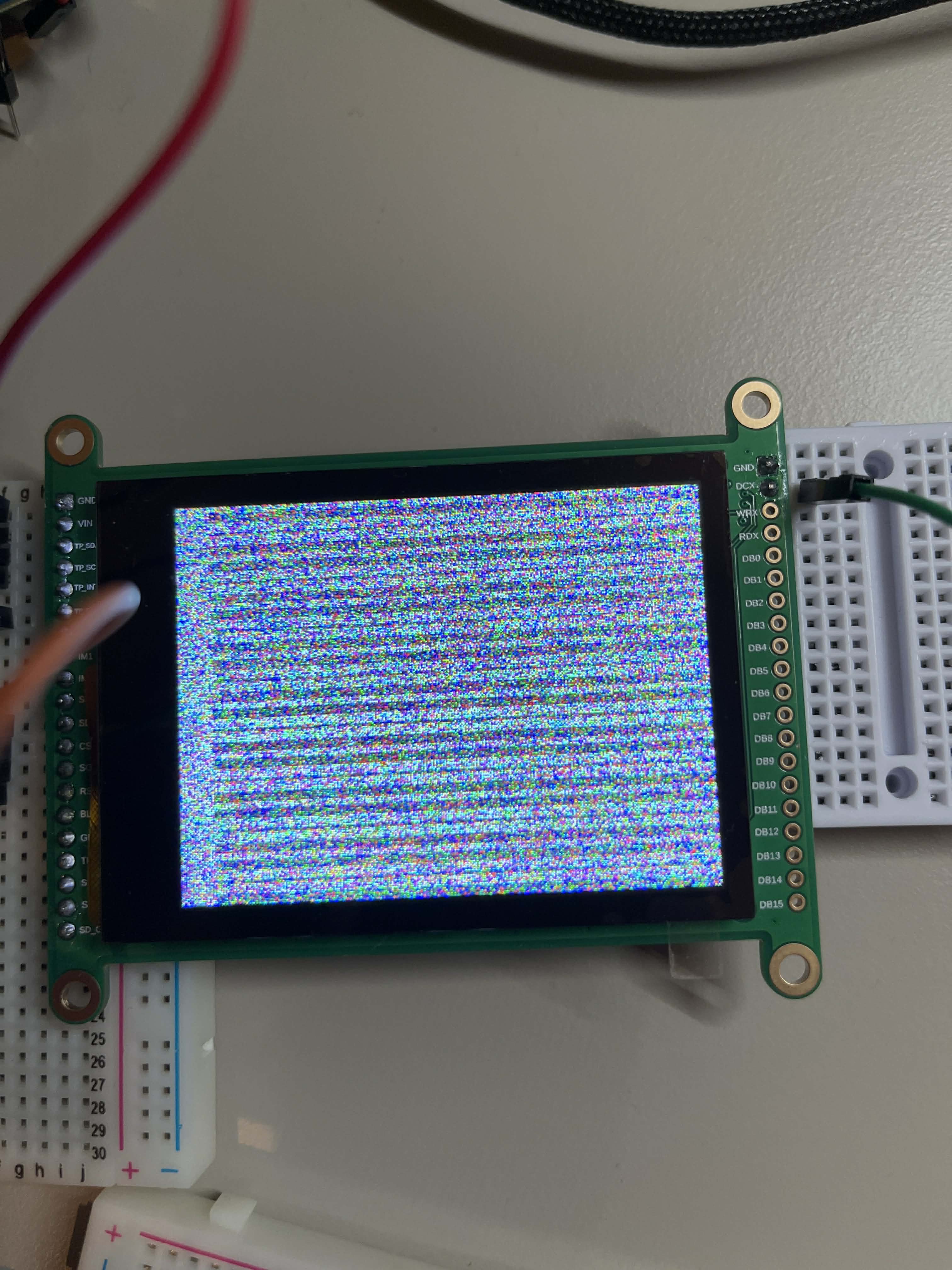
Issue: There is a short circuit between the DCX pin (J1 pin 2) and the SCL pin (J2 pin 13) on the breakout PCB. Measured resistance between these two pins is approximately 0.5 ohms with no external wiring connected and no power applied to the board.
How I found it: While debugging why the display was not initializing over 4-wire SPI, I performed continuity checks between all signal pins. The multimeter beeps between DCX (J1-2) and SCL (J2-13), confirming a direct low-resistance connection that should not exist according to the datasheet.
Expected behavior: According to the product datasheet, DCX (J1-2) and SCL (J2-13) are completely independent signals with no internal connection between them.
Impact: In 4-wire SPI mode, the D/CX line is continuously corrupted by the SPI clock signal, making it impossible to initialize the ST7789VI display controller correctly.
Board details:
- Part number: NHD-2.8C-CSXP-BREAKOUT
- Interface configured: 4-wire SPI (R2, R3, R5 closed; R1, R4, R6 open)
- Tested with: STMicroelectronics B-U585I-IOT02A Discovery Kit (STM32U585)
- Zephyr RTOS with ST7789V display driver
Could you please advise on a replacement or repair? I am happy to provide photos or additional measurements if needed.
Thank you.
-

I have been trying to two days get the resistive touch version to work in 4-wire SPI. It looks like my board has the same short as yours.
Details:
- Part number: NHD-2.8R-CSXP-BREAKOUT
- Interface configured: 4-wire SPI (R2, R3, R5 closed; R1, R4, R6 open)
- Tested with: ESP32-C6-DevKitC-1
- Zephyr RTOS (latest) with ST7789V display driver
0 -
hieu trong found something. Look at the datasheet for the display. Pin 11 is DCX and described as:
Parallel Interface:
Data / Command selection: ‘1’ = Data ; ‘0’ = Command
Serial Interface:
Serial Clock SignalSo they are supposed to be the same pin it appears. Looking at the datasheet for the ST7789 it looks like the WRX pin is the DCX for 4-pin SPI. So one pin over on the breakout. Finally got it working!
Here is my current device tree overlay:
mipi_dbi {
    compatible = "zephyr,mipi-dbi-spi";
    spi-dev = <&spi2>;
    reset-gpios = <&gpio0 23 GPIO_ACTIVE_LOW>;
    dc-gpios = <&gpio0 22 GPIO_ACTIVE_HIGH>;
    #address-cells = <1>;
    #size-cells = <0>;

    st7789v_240x320: st7789v@0 {
       compatible = "sitronix,st7789v";
       mipi-max-frequency = <20000000>;
       reg = <0>;
       width = <240>;
       height = <320>;
       x-offset = <0>;
       y-offset = <0>;
       mdac = <0x80>;
       colmod = <0x55>;
       porch-param = [0c 0c 00 33 33];
       gctrl = <0x35>;
       vcom = <0x2b>;
       lcm = <0x2c>;
       vrhs = <0x11>;
       vdvs = <0x20>;
       gamma = <0x01>;
       pwctrl1-param = [a4 a1];
       pvgam-param = [d0 00 05 0e 15 0d 37 43 47 09 15 12 16 19];
       nvgam-param = [d0 00 05 0d 0c 06 2d 44 40 0e 1c 18 16 19];
       cmd2en-param = [5a 69 02 01];
       ram-param = [00 f0];
       rgb-param = [cd 08 14];
       mipi-mode = "MIPI_DBI_MODE_SPI_4WIRE";
    };
};
0 -
Engineering Support it looks like this is correctly documented for the NHD-2.8-240320AF-CSXP-F but the -FT and -FCTP documentation need updating. None of the NHD-2.8-CSXP-BREAKOUT variants seem to document this pin correctly either.
0 -

Hi,
The SCL and DCX pins on the breakout board are tied together because they serve different functions depending on the interface being used. In the parallel interface, the pin functions as the Data/Command signal, while in the serial interface, it functions as the serial clock signal.
Thank you for pointing out the confusion in the specification pinout. We will review and update the documentation and upload the revised version as soon as possible.
0 -
Wow, many thanks Thomas Brezinski, works instantly when switching to WRX pin.
That definitely the document confusion here, I was scratching my head for the last weekend.
Cheers!
0
Please sign in to leave a comment.
Comments
5 comments