Issue with External Character (CG RAM) Output on NHD-240128WG-ATFH-VZ#

Dear Newhaven Display Support Team,
I am currently developing a system using the NHD-240128WG-ATFH-VZ# LCD model.
While the standard text and graphic outputs are functioning correctly, I am experiencing difficulties implementing the External Character (CG RAM) functionality and would appreciate your assistance.
[Symptoms]
-
I attempted to output custom characters via CG RAM, but they are not being displayed properly.
-
During the debugging process, I observed that the custom characters occasionally flicker on the screen momentarily and then immediately disappear.
-
Based on this, I suspect that the CG RAM address (Offset) configuration is likely correct, but an error occurs during the maintenance or refreshing of the data.
Could you please verify if this behavior is due to a hardware limitation or an issue with the software configuration? Below is the relevant part of my current implementation.
[Source Code]
/**
* LCD Initialization
*/
void LCD_Init()
{
// Font selection: Low = 8x8, High = 6x8
HAL_GPIO_WritePin(GPIOB, LCD_FS_Pin, GPIO_PIN_RESET);
// Disable Inversion (Reverse)
HAL_GPIO_WritePin(GPIOF, LCD_RV_Pin, 0);
// Reset the display by toggling the Reset pin
HAL_GPIO_WritePin(GPIOF, LCD_RESET_Pin, GPIO_PIN_RESET);
HAL_Delay(10);
HAL_GPIO_WritePin(GPIOF, LCD_RESET_Pin, GPIO_PIN_SET);
HAL_Delay(10);
// Set control pins to initial HIGH state
LCD_SetRD(1);
LCD_SetWR(1);
LCD_SetCD(1); // C/D = High
HAL_Delay(30); // Wait for power supply stabilization
// Set Text Home Address
LCD_WriteData(0x00);
LCD_WriteData(0x00);
LCD_WriteCommand(0x40);
// Set Graphic Home Address = 0x4000
LCD_WriteData(0x00);
LCD_WriteData(0x40);
LCD_WriteCommand(0x42);
// Set Text Area (Number of characters per line)
LCD_WriteData(TEXT_AREA);
LCD_WriteData(0x00);
LCD_WriteCommand(0x41);
// Set Graphic Area (Same as Text Area)
LCD_WriteData(TEXT_AREA);
LCD_WriteData(0x00);
LCD_WriteCommand(0x43);
// Set CG RAM Offset
LCD_WriteData(0x0F); // CG RAM AREA: 0x7800 (Offset 0x0F)
LCD_WriteData(0x00);
LCD_WriteCommand(0x22);
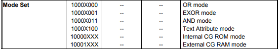
// Set Display Mode: OR mode (Text/Graphic overlap) & Internal CG ROM mode
LCD_WriteCommand(0x80);
// Display ON: Text ON, Graphic ON
LCD_WriteCommand(0x9C);
HAL_Delay(10); // Short delay after initialization commands
}
/**
* Write External Character to CG RAM AREA
*/
void LCD_LoadCustomChar(uint8_t code, const uint8_t* pattern)
{
// Calculate start address based on CG RAM AREA offset
uint16_t startAddr = 0x7800 + (code * 8);
// Set Address Pointer
LCD_WriteData(startAddr & 0xFF); // Address Lower 8-bit
LCD_WriteData((startAddr >> 8) & 0xFF); // Address Upper 8-bit
LCD_WriteCommand(0x24);
// Continuous 8-byte data write
LCD_WriteCommand(0xB0); // Data Auto Write Start
for (uint16_t i = 0; i < 8; i++)
{
LCD_WriteData(pattern[i]);
}
LCD_WriteCommand(0xB2); // Data Auto Write Reset (End)
}
I look forward to your professional feedback on this matter.
Best regards,
-

Hello,
I took a look at your code and noticed you are setting the display to be in internal ROM mode during your initialization here:
// Set Display Mode: OR mode (Text/Graphic overlap) & Internal CG ROM mode
    LCD_WriteCommand(0x80);
In the datasheet for the display, we can see that you can set the mode to be External CG RAM mode here:
Can you edit the initialization of the display to see if this fixes the issue?
0 -
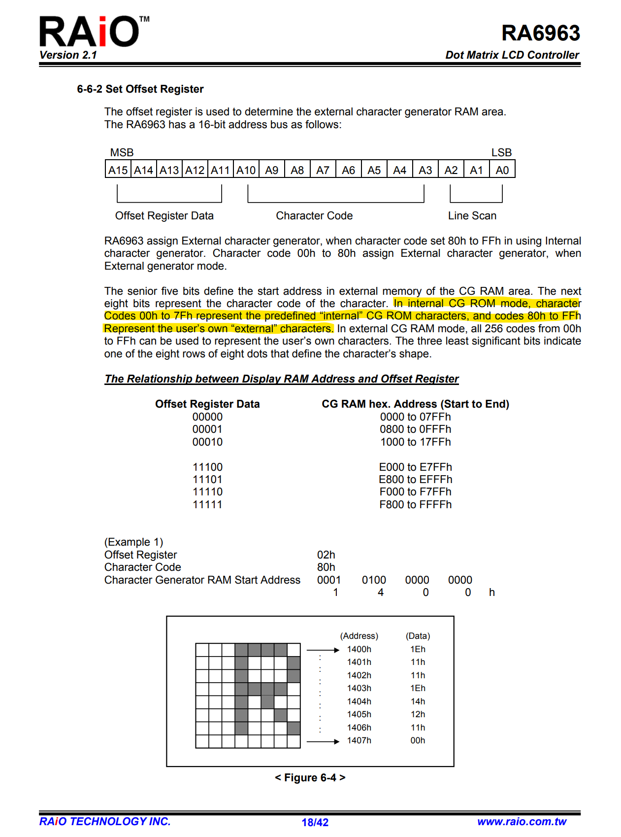
Nothing shows up when I use External CG RAM mode. Also, looking at the RA6963 datasheet, it says user-defined characters can be used starting from 80H even in CG ROM mode.
 0
0 -
Hello,
Could you please send the full source code? I want to see how the LCD_WriteData and LCD_WriteCommand functions work
0 -
Here are two pieces of code. The first is the LCD code, and the second is the main code.
// Configure CE pin. 0=low, 1=high
static void LCD_SetCE(uint8_t x)
{
    HAL_GPIO_WritePin(GPIOF, LCD_CE_Pin, x);
}

// Configure C/D(RS) pin. 0=low(Data), 1=high(Command)
static void LCD_SetCD(uint8_t x)
{
    HAL_GPIO_WritePin(GPIOF, LCD_CD_Pin, x);
}

// Configure RD pin. 0=low, 1=high
static void LCD_SetRD(uint8_t x)
{
    HAL_GPIO_WritePin(GPIOF, LCD_RD_Pin, x);
}

// Configure WR pin. 0=low, 1=high
static void LCD_SetWR(uint8_t x)
{
    HAL_GPIO_WritePin(GPIOF, LCD_WR_Pin, x);
}

// Write 8-bit parallel data to the data bus
static void LCD_WriteDataBus(uint8_t data)
{
    // Write data to each pin individually (bit-banging)
    HAL_GPIO_WritePin(GPIOF, GPIO_PIN_0, (data & (1 << 0)) ? GPIO_PIN_SET : GPIO_PIN_RESET);
    HAL_GPIO_WritePin(GPIOF, GPIO_PIN_1, (data & (1 << 1)) ? GPIO_PIN_SET : GPIO_PIN_RESET);
    HAL_GPIO_WritePin(GPIOF, GPIO_PIN_2, (data & (1 << 2)) ? GPIO_PIN_SET : GPIO_PIN_RESET);
    HAL_GPIO_WritePin(GPIOF, GPIO_PIN_3, (data & (1 << 3)) ? GPIO_PIN_SET : GPIO_PIN_RESET);
    HAL_GPIO_WritePin(GPIOF, GPIO_PIN_4, (data & (1 << 4)) ? GPIO_PIN_SET : GPIO_PIN_RESET);
    HAL_GPIO_WritePin(GPIOF, GPIO_PIN_5, (data & (1 << 5)) ? GPIO_PIN_SET : GPIO_PIN_RESET);
    HAL_GPIO_WritePin(GPIOF, GPIO_PIN_6, (data & (1 << 6)) ? GPIO_PIN_SET : GPIO_PIN_RESET);
    HAL_GPIO_WritePin(GPIOF, GPIO_PIN_7, (data & (1 << 7)) ? GPIO_PIN_SET : GPIO_PIN_RESET);
}

// Write a command to the LCD
static void LCD_WriteCommand(uint8_t cmd)
{
    LCD_SetCD(1);   // C/D High = Command mode
    LCD_SetCE(0);   // Chip Enable Active

    LCD_WriteDataBus(cmd); // Output command byte to bus

    LCD_SetWR(0);   // Write strobe Low
    LCD_SetWR(1);   // Write strobe High (Latch)
    LCD_SetCE(1);   // Chip Disable
}

// Write data to the LCD
static void LCD_WriteData(uint8_t data)
{
    LCD_SetCD(0);   // C/D Low = Data mode
    LCD_SetCE(0);   // Chip Enable Active

    LCD_WriteDataBus(data); // Output data byte to bus

    LCD_SetWR(0);   // Write strobe Low
    LCD_SetWR(1);   // Write strobe High (Latch)
    LCD_SetCE(1);   // Chip Disable
}

/**
 * LCD Initialization
 */
void LCD_Init()
{
    // Font selection: Low = 8x8, High = 6x8
    HAL_GPIO_WritePin(GPIOB, LCD_FS_Pin, GPIO_PIN_RESET);

    // Disable Inversion (Reverse Display)
    HAL_GPIO_WritePin(GPIOF, LCD_RV_Pin, 0);

    // Hardware Reset: Toggle the Reset pin
    HAL_GPIO_WritePin(GPIOF, LCD_RESET_Pin, GPIO_PIN_RESET);
    HAL_Delay(10);
    HAL_GPIO_WritePin(GPIOF, LCD_RESET_Pin, GPIO_PIN_SET);
    HAL_Delay(10);

    // Set control pins to initial HIGH state (Idle)
    LCD_SetRD(1);
    LCD_SetWR(1);
    LCD_SetCD(1);  // Default Command Mode
    HAL_Delay(30); // Stabilization delay

    // Set Text Home Address (0x0000)
    LCD_WriteData(0x00);
    LCD_WriteData(0x00);
    LCD_WriteCommand(0x40);

    // Set Graphic Home Address (0x4000)
    LCD_WriteData(0x00);
    LCD_WriteData(0x40);
    LCD_WriteCommand(0x42);

    // Set Text Area (Number of columns/characters per line)
    LCD_WriteData(TEXT_AREA);
    LCD_WriteData(0x00);
    LCD_WriteCommand(0x41);

    // Set Graphic Area (Same width as Text Area)
    LCD_WriteData(TEXT_AREA);
    LCD_WriteData(0x00);
    LCD_WriteCommand(0x43);

    // Set CG RAM Offset
    LCD_WriteData(0x0F); // CG RAM Area start: 0x7800 (Offset 0x0F)
    LCD_WriteData(0x00);
    LCD_WriteCommand(0x22);

    // Set Display Mode: Logical OR (Text/Graphic overlap) & Internal CG ROM
    LCD_WriteCommand(0x80);

    // Display ON: Enable both Text and Graphic layers
    LCD_WriteCommand(0x9C);

    HAL_Delay(10); // Small delay post-initialization
}

/**
 * Write a custom character pattern to CG RAM
 * @param code: Character code index (0-255)
 * @param pattern: Pointer to 8-byte font data
 */
void LCD_LoadCustomChar(uint8_t code, const uint8_t* pattern)
{
    // Calculate start address based on CG RAM offset
    uint16_t startAddr = 0x7800 + (code * 8);

    // Set Address Pointer
    LCD_WriteData(startAddr & 0xFF);         // Address LSB
    LCD_WriteData((startAddr >> 8) & 0xFF);  // Address MSB
    LCD_WriteCommand(0x24);

    // Data Auto Write sequence
    LCD_WriteCommand(0xB0); // Start Auto Write
    for (uint16_t i = 0; i < 8; i++)
    {
        LCD_WriteData(pattern[i]);
    }
    LCD_WriteCommand(0xB2); // End Auto Write (Reset)
}

/**
 * Display a character at a specific pixel location
 * @param x: 0 ~ 239 (Pixel x-coordinate). Consider font width.
 * @param y: 0 ~ 127 (Pixel y-coordinate). Consider font height.
 * @param text: Character code to display
 */
void LCD_DrawAt(uint8_t x, uint8_t y, const uint8_t text)
{
    // Convert pixel coordinates to memory-mapped grid positions
    uint8_t pointX = x / FONT_WIDTH;
    uint8_t pointY = y / 8;

    // Calculate memory address based on text area width
    uint16_t addr = (pointY * TEXT_AREA) + pointX;

    // Set address pointer (LCD cursor position)
    LCD_WriteData(addr & 0xFF);          // LSB
    LCD_WriteData((addr >> 8) & 0xFF);   // MSB
    LCD_WriteCommand(0x24);

    // Output character code from CGROM/CGRAM
    LCD_WriteData(text);
    LCD_WriteCommand(0xC4); // Data write and increment ADP
}
const uint8_t FONT_ARROW_UP[8] = {0x04, 0x0E, 0x1F, 0x04, 0x04, 0x04, 0x04, 0x00}; // Up Arrow icon
const uint8_t FONT_ARROW_LEFT[8] = {0x00, 0x04, 0x08, 0x1F, 0x08, 0x04, 0x00, 0x00}; // Left Arrow icon
uint8_t num = 0;
int main(void)
{
LCD_Init();
// Register custom characters to CG RAM
LCD_LoadCustomChar(0x80, FONT_ARROW_UP); // Register Up Arrow at 0x80
LCD_LoadCustomChar(0x81, FONT_ARROW_LEFT); // Register Left Arrow at 0x81
LCD_LoadCustomChar(0x00, FONT_ARROW_UP); // Register Up Arrow at 0x00
LCD_LoadCustomChar(0x01, FONT_ARROW_UP); // Register Up Arrow at 0x01
HAL_Delay(2000);
// Display various characters at specific coordinates
LCD_DrawAt(30, 100, 0x80); // Custom Up Arrow
LCD_DrawAt(45, 100, 0x77); // Default 'w'
LCD_DrawAt(60, 100, 0x01); // Custom Up Arrow
LCD_DrawAt(75, 100, 0x81); // Custom Left Arrow
LCD_DrawAt(90, 100, 0x02); // Empty/Undefined
while(1)
{
// Dynamic character update loop
LCD_DrawAt(15, 100, 0x00 + num);
HAL_Delay(1000);
}
}0 -
Hello,
Thank you for providing the code. I wanted to ask, did you manage to get the display working without the custom characters? Just displaying basic shapes or characters.
0 -
Yes, the image was rendered exactly as provided in the sample code.
Also, the text is being displayed accurately at the specific coordinates I wanted.
0 -
Could you try sending the command first before the data for the LCD_DrawAt() function? See the modified code here:
void LCD_DrawAt(uint8_t x, uint8_t y, const uint8_t text)
{
    // Convert pixel coordinates to memory-mapped grid positions
    uint8_t pointX = x / FONT_WIDTH;
    uint8_t pointY = y / 8;

    // Calculate memory address based on text area width
    uint16_t addr = (pointY * TEXT_AREA) + pointX;

    // Set address pointer (LCD cursor position)
    LCD_WriteCommand(0x24);              // Send command first
    LCD_WriteData(addr & 0xFF);          // LSB
    LCD_WriteData((addr >> 8) & 0xFF);   // MSB

    // Output character code from CGROM/CGRAM
    LCD_WriteCommand(0xC4); // Data write and increment ADP // send command first
    LCD_WriteData(text);
}
0 -
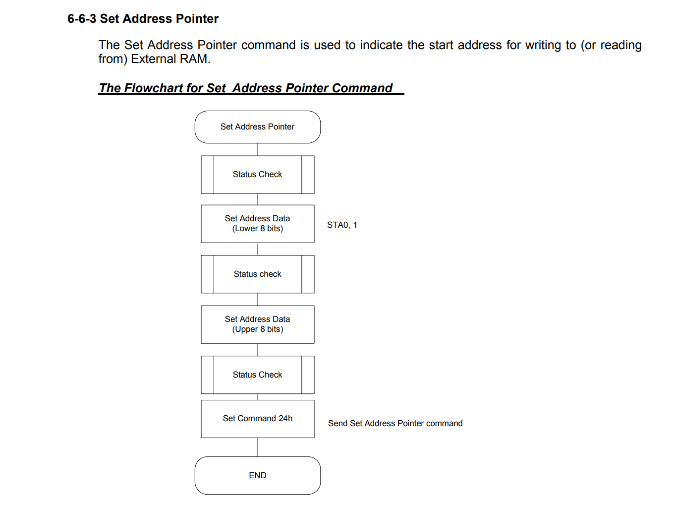
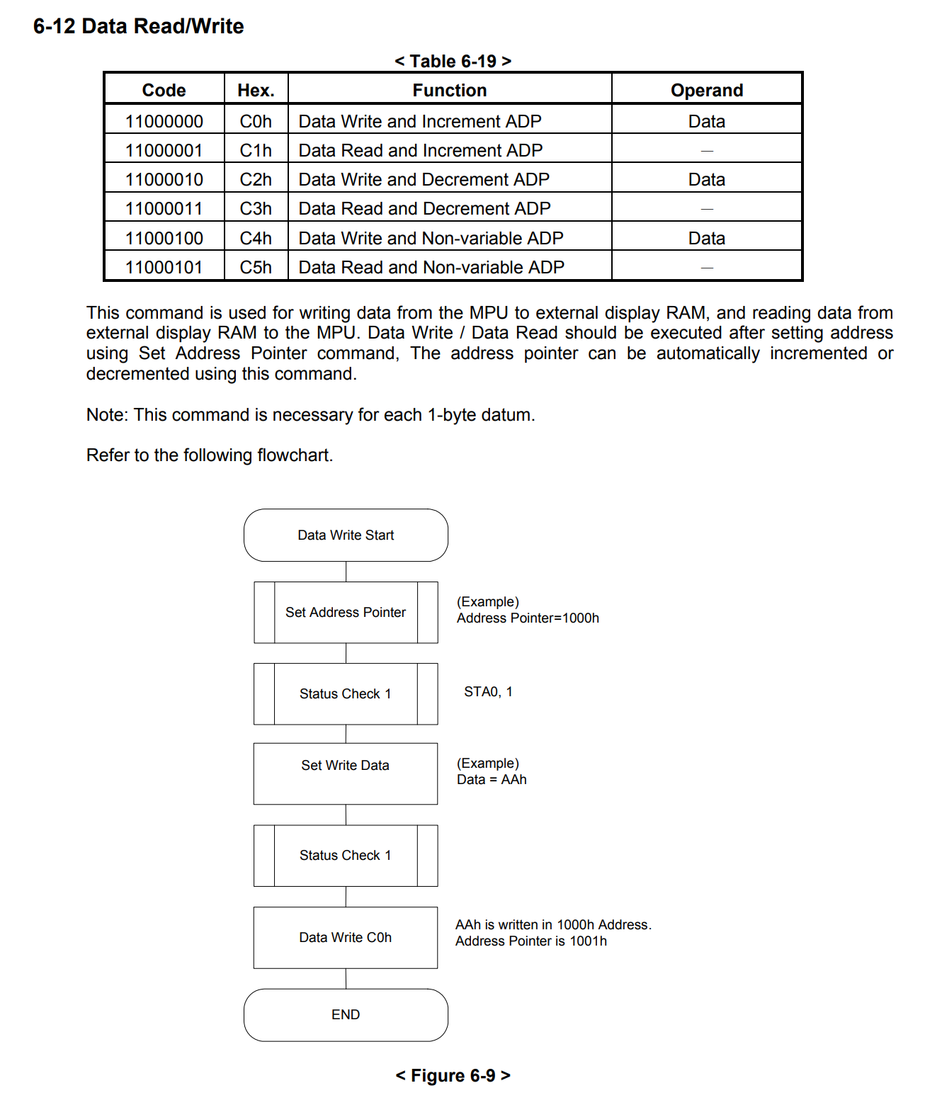
If we do it this way, even the parts that were displaying correctly will stop working. According to the RA6963 datasheet, the flowchart is structured so that data is sent first, followed by the command.
 0
0 -
Hello,
My apologies, you are right. I looked at your code again and saw this at initialization:
// Set Text Area (Number of characters per line)
    LCD_WriteData(TEXT_AREA);
    LCD_WriteData(0x00);
    LCD_WriteCommand(0x41);

    // Set Graphic Area (Same as Text Area)
    LCD_WriteData(TEXT_AREA);
    LCD_WriteData(0x00);
    LCD_WriteCommand(0x43);
Could you set the graphic area and the text area in different parts of the screen so they are not overlapping and see if that works?
Could you also try setting the display mode to EXOR and see if that fixes the issue?
0
Please sign in to leave a comment.
Comments
9 comments