NHD-0416BZ: Unable to get stable operation. Am I initializing properly?
Answered
Hi all,
I'm working on some code to get a NHD-0416BZ Character Display up and running in 4-bit mode on a microcontroller.
A few days in and I've had no luck getting characters to reliably display, and even getting the display up and running with a blinking cursor is proving more challenging than expected.
I wrote my code following the examples provided in the display datasheet as well as looking at the code example provided for the NHD-0240AZ (here) since it uses the same controller . My goal for now is to get the display up and to show a few characters.
Looking at the data on a logic analyzer, it all seems to check out as far as the data sent over the bus, but for some reason the display itself either does nothing, shows a cursor, on occasion moves the cursor around each time I reset the Microcontroller.
Here is what the bus signals look like for my initialization routine: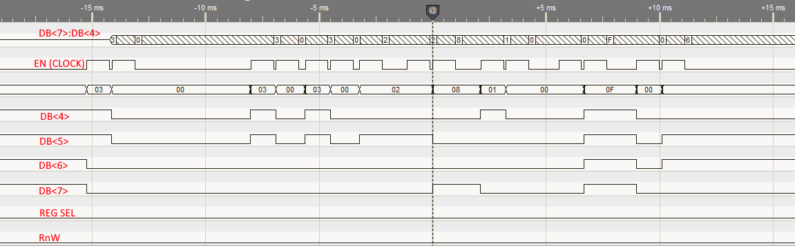
I am sending the following:
0x30 - Wake Up #1
5ms Delay
0x30 - Wake Up #2
160us Delay
0x30 - Wake Up #3
160us Delay
0x2 - Set 4-Bit Mode (send only 0x2 nibble?)
1ms Delay
0x28 - Function Set: 4Bit/2Line (this is a 4-line display, assuming should set 2 instead of 1?)
1ms Delay
0x10 - Set Cursor: I'm not sure why this is here, but it's in the 0416 example
1ms Delay
0x0F - Display ON: Entire Display/Cursor On/Blink Enabled
0x06 - Entry Mode Set: Cursor Move Right/No Shift
Once all this is sent, the display appears blank, no cursor, nothing, so I figure something must be funky in the initialization. Either the commands themselves that I'm sending, or maybe a timing issue?
I do have questions about the initialization routine, since there seems to be conflicting information between the NHD-0240AZ 4-bit initializing sequence and the sequence shown in the NHD-0416BZ code example despite use of the same ST7066U controller.
- The example 4-Bit init() routine for the 0416 seems to put out the 0x3 nibble onto the bus and clock it 3 times. The 0420 example sends the full 0x30 byte 3 times. Which is correct here?
- The 0416 example sends a 0x2 nibble after the triple 0x3 sequence. The 0420 example has a code comment saying to send 0x3, but actually sends 0x2. See below, note how the comment says 0x30, but the code is passing 0x20, and even then, it's only clocking out the top 4 bits. Which is correct?
-
  void init_4Bit(){       // Initialization Sequence for 4-Bit Interface
    Set_4Bit(0x20);       // Function Set command for display initialization.
    command(0x28);        // Function Set command with setting: 4-Bit / 2 Line

    command(0x0D);        // Display ON; Cursor OFF; Blinking ON;
    command(0x06);        // Entry Mode set
  }

  void Set_4Bit(char i){    // Write 0x30 to parallel bus for 4-Bit Initialization Setting.
    PORTD = i;
    digitalWrite(RS, LOW);          // Register Select: Command
    digitalWrite(RW, LOW);          // Read/Write Select: Write

    digitalWrite(EN, HIGH);         // Toggle enable signal to latch data.
    delay(1);
    digitalWrite(EN,LOW);
    delay(1);
  }
I'm unsure how I should proceed from here. Would someone be able to give some insight as to what initialization routine I should be using? And if what I have should be good, perhaps some kind of timing issue I could look into?
Thanks!
-

Hi Kyle,
Could you please provide your schematic or wiring diagram for your setup? While both the displays have the same IC, the initialization is different. Your initialization commands seem right.
Could you also provide your code so we can review?
0 -
The schematic for the LCD connection is below. I have R72 loaded instead of R71 to run the LCD at 5V.
I have also loaded R70 to turn on the backlight P2[0]-P2[6] are the microcontroller pins. The pins are set for Open-Drain Drive Low on D7-D4 (P2[3]-P2[0]). The control lines (RS/RnW/EN) are all strong drive outputs: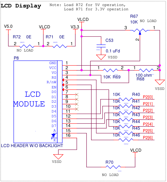
The code I have is here. Note CyDelay() calls are ms, CyDelayUs() calls are us. The actual initialization function (NHD_Init()) is at the bottom of the code posted here. Note that it is called 300ms after POR to allow for any/all voltages to get stable:/*NHD_WriteNib() - Pulses EN for 1ms to clock/latch data*/
static void NHD_WriteNib(void){
LCD_E_Write(1);
CyDelay(1);
LCD_E_Write(0);
CyDelayUs(100);
}
/*NHD_SendCommand() - Writes specified byte to port and clocks it out.  4-Bit Mode, 2 clocks*/
void NHD_SendCommand(uint8_t byte, bool busycheck){
    LCD_DATA_OUT_Write(byte);   //Data onto port
    CyDelayUs(10);      //Setup time to ensure all pins are changed before clocking
    LCD_RS_Write(0);    //RS=0 : Command
    LCD_RnW_Write(0);   //Write
    NHD_WriteNib();     //Clock out
    byte = byte << 4;   //Shift next nibble
    LCD_DATA_OUT_Write(byte);   //Next nibble onto port MSb
    CyDelayUs(10);      //Setup time to ensure all pins are changed before clocking
    NHD_WriteNib();     //Clock out
    CyDelayUs(10);

    if (busycheck){
        //Not doing an actual busy check yet, just inserting a delay for now
        CyDelayUs(200);
    }
}
/*NHD_WakeSeq_Byte - Writes full 0x30 byte to Display 3 times to issue wake sequence*/
void NHD_WakeSeq_Byte(void){
    NHD_SendCommand(0x30, 0);   //Wake1 - 5ms
    CyDelay(5);
    NHD_SendCommand(0x30, 0);   //Wake2 - 160us
    CyDelayUs(160);
    NHD_SendCommand(0x30, 0);   //Wake3 - 160us
    CyDelayUs(160);
}
/*NHD_Set_4Bit(void) - Issues 0x2 nibble onto bus and clocks it out to display*/
void NHD_Set_4Bit(void){
LCD_DATA_OUT_Write(0x20); //Put data on to port
NHD_WriteNib();
CyDelay(1);
}/*NHD_Init() - Initializes NHD-0216*/
void NHD_Init(void){
LCD_E_Write(0);
LCD_RnW_Write(0);
LCD_RS_Write(0);
CyDelay(100);
NHD_WakeSeq_Byte(); //Wake sequence
NHD_Set_4Bit(); //Initialize to 4-Bit
NHD_SendCommand(0x28, 0); //Function Set - 4Bit/2Line
CyDelayUs(200);
NHD_SendCommand(0x10, 1); //Set Cursor
CyDelayUs(200);
NHD_SendCommand(0x0F, 1); //Display ON/Cursor ON/Blinking ON
CyDelayUs(200);
NHD_SendCommand(0x06, 1); //Entry Mode Set
CyDelay(100);
}0 -
Hi Kyle,
Thank you for sending the schematic and code. I've reviewed the schematic and it seems the voltage for the contrast is too low. I see you are using a voltage divider with 10K Ohm and 100 Ohm resistors. I calculated the output at 5V going through your voltage divider and it only gets to 0.05V.
I suggest hooking up a potentiometer or just playing around with the voltage divider values for R69 and R68 until you get something to show up on the display.
0 -
It's odd, because last week when I was trying to get this up and running I was able to get (wrong) characters to appear. I.E. I would attempt to print "123" and would get "133" or "122" or sometimes some of the asian characters in the font table would appear. They would appear at various points on the display, like it was not returning the cursor to home like it should have been. This was also when I was messing around alot with the timings while writing the functions in my above post. So far this week I haven't been able to recreate this behavior.
I should share some other details about how I've had this LCD connected. Originally, with this kit being set to run the LCD at 3.3V (regardless of if the kit VDD was set for 3.3V or 5V, the LCD would always be supplied 3.3V when R71 was loaded), I ran all the signals from the kit into a breadboard that allowed me to supply the LCD w/ 5V. Last Friday I decided rather than going through the breadboard (which could maybe be causing some kind of problem? Noise maybe?) I made the modification to move the R71 resistor to R72 so I could supply 5V through the actual LCD connector.
The potentiometer R67 on this eval board is DNL, so I don't actually have a pot there. However, I luckily have an analog pot populated elsewhere on the kit I can connect Vo to, but it did mean I had to re-introduce the breadboard so I could break the Vo signal out. I did so and adjusted the voltage coming into Vo to 0.5V as specified on the NHD-0416 data sheet. I still most of the time get a blank screen on initialization. On occasion on a power cycle I may get a (static, not blinking) cursor. I have a photo of the LCD showing this below: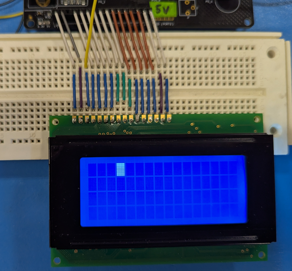
Most of the time this cursor does not show up. Maybe once out of 3 power cycles? The rest of the time I just get a blank screen like I have been seeing all this week. Needless to say I still cannot seem to get any characters to display.0 -
Hello Kyle,
Thank you for the added information. I took a look at your schematic again and noticed you have series resistors connected to the parallel data lines to the display. Can you remove the resistors and connect the data lines directly to the display and see if that works?
The voltage level for the data lines should be ideally the same as the VDD. This could be causing the intermittent or wrong character being displayed on the screen.
0 -
I think you were dead on. I moved the data lines onto a different port of the MCU entirely that doesn't have those series 10k resistors. Since you brought voltage level up, yes I think I was getting at least some stuff on the display last week was because I had the pins set to strong drive. Right now they are set to Open-Drain (Pulls low) since I saw in the datasheet that there are pull-ups on the display side, so those 10ks were creating a resistor divider with the pull-ups on the data lines of the display. I took some measurements of the levels on the scope and sure enough they were not even close to 5V high (and pulling low wasn't getting to 0V either).
Looks like that was the issue. It's currently a mess in terms of wiring, but I'm now getting text: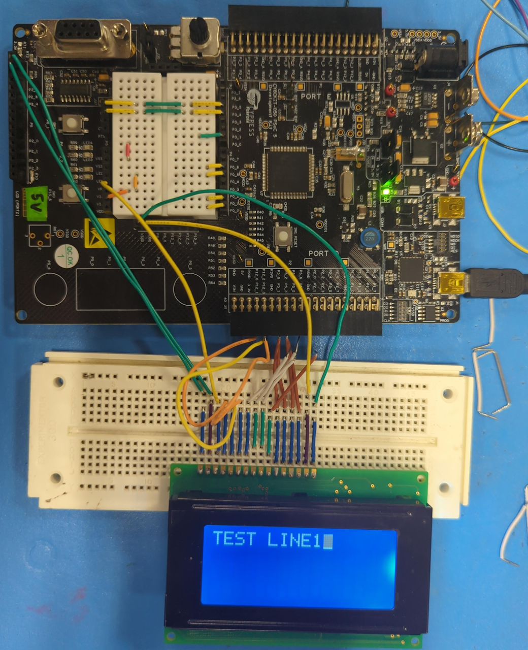
Thank you for the help!0 -
Hi Kyle,
That's good to hear! Let me know if you have any more concerns. I'll gladly assist you.
0
Please sign in to leave a comment.
Comments
7 comments